Guide to replace the iPhone 4s wifi antenna


To open the lid it is necessary to remove two "pentalobe" screws.
Use a suitable screwdriver.


Press with your fingers forward to move the lid.


Remove the battery cover.


The battery connector is supported by two Phillips screws.
Remove the part under the upper screw colored green and keep it. Due to its size it is very easy to lose it.


Disconnect the battery with a plastic tool so as not to damage the board or the connector.


Pull the plastic strip to detach the battery.


Remove the connector cover. It is secured with two 1.5 and 1.2 mm Phillips screws.


With the help of an opening tool disconnect and separate the flex cable.


Disconnect the coaxial cable from the motherboard.


Remove the two 2.4mm Phillips screws.
Do not lose the piece of plastic that will be loose after the screw on the left.


The lower module is attached to the chassis. You must pry gently with an opening tool to release it.


Remove the screws from the cover:


Disconnect the connectors from the motherboard:


The camera is held by the connector to the motherboard.
Unplug it with an opening tool.


Remove the clip that is attached with a 1.5mm Phillips screw.


Use a flat screwdriver to remove the 4.8mm Standoff screw
Disconnect the flex cable from the WIFI antenna.


Remove the screws that hold the motherboard:
Parte inferior:


Holding it from the bottom, remove the motherboard carefully.


Remove and make sure not to lose the component that acts as a mass of the camera.


Remove the protection attached to the screw in the upper left corner.


Remove the 4 Phillips screws from the 4 corners of the equipment.


Unscrew the screws that hold the display about one turn.
It is not necessary to remove them, with loosening them it is enough to extract the display.


Insert an opening tool into the joint between the display and the chassis.
Move it around the contour by gently prying it loose to release the display.


Separate the display from the chassis with care that the connectors do not get caught.
When reassembling the display, make sure that the flex cable and connector of the digitizer has passed through its slot. If you do not insert it well you can break it by the small fold that it has.


The camera is held by a metal support with three notches. To remove it, simply pry gently, we recommend a curved tip tool.
When reassembling it must fit the three notches of the small shield or support.


Pull gently on the flex cable to remove the camera.


Remove the 2 brackets that hold the headset and the sensor.


Carefully peel off the headset, as well as the flex cable.


Remove the two 1.6mm Phillips screws that hold the power button.


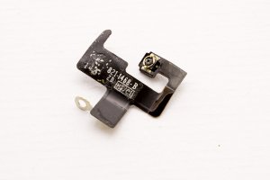
Carefully take off the flex of the wifi antenna.
In addition to gluing it is attached by a 2.4mm Phillips screw.
