Guide with all the necessary steps so that you can change the components of the CAT B35 Phone yourself.


We start by removing the ten hexagonal screws (H1.3) back and the two Phillips screws (PH # 00) that are hidden behind the cover of the USB connector.


With an opening tool, we will leverage to disengage it.


We remove the nine Phillips screws (PH # 00) that hold the battery shield and the base plate. Then we disconnected the battery and removed it.


We remove the SIM tray and we pry the upper part of the base plate to disengage it.


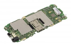
We take off the screen and desoldamos it of the motherboard to be able to retire it.


All that remains is to desolder the camera from the motherboard.